
Introduction to Piezo-electric Accelerometers
Preface
An accelerometer is a transducer that converts physical acceleration, vibration or shock into an electrical output that can be measured. These parameters can be quite destructive and hence the need to quantify them. There are several different types of accelerometer, with each one having features that make it suitable for a specific task. The piezo-electric (PE) accelerometer remains the most effective device for the measurement of shock and vibration mainly due to its robustness and ability to survive in the environment it is measuring. Other types of accelerometer, besides the PE types discussed in this document include strain gauge based (semi-conductor or bonded foil) and MEMS capacitive based designs, as well as servo accelerometers. These accelerometer designs will all measure very low frequencies down to static or ‘DC’ levels (zero Hertz), giving them the ability to respond to the earths gravitational force of 1g, however these designs usually have limited high g and high frequency capability.
Why an Accelerometer?
Vibration and shock can be specified in terms of acceleration, velocity, or displacement. These three parameters are connected mathematically for a periodic, sinusoidal motion;
A = 
Where:
A = peak acceleration
V = peak velocity
D = peak to peak displacement

f = frequency
The frequency determines the relationship between the three parameters, therefore for constant acceleration at very low frequencies, the peak to peak displacement (i.e a particle oscillating between 2 fixed points) will be large. For high frequencies at constant acceleration, the peak to peak displacement will be extremely small.
Taking this from a more practical sense, low frequency vibration is best measured as a displacement, whilst high frequency vibration is measured in terms of acceleration. For instance, tall buildings that sway due to wind force are quantified as a vibration in terms of displacement, whilst many failures due to resonance choose acceleration as the measurement parameter. For machine health monitoring of rotating machines, velocity can be chosen which is governed by an ISO standard.
Displacement is quite easy to visualize being the distance between the two extremes of the peak to peak of the measurement. This however, requires a fixed reference point for the measurement, which is not always practical. Velocity transducers and accelerometers (sensors that give an output proportional to acceleration) do not require this fixed reference point and so are much easier to use. Most velocity transducers are constructed by having a ferrous core suspended within an electrical coil that generates a voltage as the core moves due to vibration, however these sensors have a limited upper frequency range and due to moving parts, prove not to be very robust. There are types of accelerometer that employ a moving mass as the means of generating an electrical output, but these also are limited in frequency like the velocity transducers. The piezo-electric accelerometer is a sensor that has no moving parts making it both extremely robust and reliable. Furthermore, the PE (piezo-electric) accelerometer as it has become known, can operate over a very wide frequency range making it the most popular choice for measurement of vibration and shock, and with integration of the vibration signal it is possible to also measure velocity and even displacement if the conditions are right.
Units of Measurement
Depending where you are in the world both Imperial and Metric units are still in use. These two sets of units cross over quite easily for displacement and velocity, but for acceleration it is either Metric values or ‘g’.
When the apple allegedly fell on Isaac Newton’s head, the impact force was governed by the acceleration due to gravity. This acceleration gives us a neat and universal way of specifying acceleration, which is ‘g’. In metric terms one ‘g’ is equal to 9.81 m/sec2, and in imperial terms to 32 ft/sec2. Had the apple been subject to an external force and accelerated at 10g, Isaac Newton may not have survived to relate his experience.
Piezo-Electric Accelerometer – Principle of Operation
 The piezo-electric phenomena is produced by certain materials that have the ability to generate an electric charge when dynamically loaded. Not only will an applied mechanical stress generate a voltage, but also an applied voltage will change the shape of the solid by a small amount (up to a 4% change in volume). These materials are classed as insulators, but do have some electric resistance – referred to as insulation resistance. If a piece of piezo-electric material is placed on a surface, then a mass placed on top of that material, there would be a measurable positive charge generated between the mass and the surface. Moreover, the charge would only increase whilst the mass was being lowered onto the material, and in the steady state this charge should remain constant. However, the electrical resistance across the surfaces of the piezo-electric material will cause that charge to leak away to nothing over a period of time. When the mass is removed, the opposite occurs in that a measurable negative charge is generated across the surfaces of the material. Taking away the effects of leakage of the charge, the magnitude of the positive charge generated will be equal to the magnitude of the negative charge generated. The insulation resistance of the piezo-electric material therefore can affect the performance of a PE accelerometer in low frequency motion.
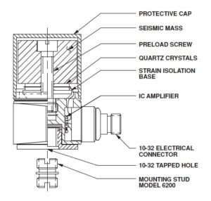
This forms the basis of a PE accelerometer in that a seismic mass is suspended from the accelerometer mounting surface via some piezo-electric material and any vibration will cause the mass to impart a force in both directions to the piezo-electric material, which therefore gives an electrical charge output proportional to the amplitude of the vibration. Furthermore, as the piezo-electric material does not generate a charge in the steady state, the PE accelerometer offers an output only when moved either by vibration or shock.
Piezo-Electric Materials
Piezo-electric properties can be found both in natural and synthetic materials. Crystals that occur naturally, e.g. quartz and tourmaline, produce accelerometers that are very stable (sensitivity does not drift with time or temperature), however these generally offer a relatively low charge sensitivity, therefore requiring a larger seismic mass to generate a reasonable output. Many ‘man made’ synthetic compounds now exist that mimic the piezo-electric effect and whose properties can be tailored to make an accelerometer for a specific purpose. These compounds can be used to manufacture ceramics, offering a huge advantage in that they can be moulded into any shape or size to suit the accelerometer design. When the ceramic is produced, it has no piezo-electric property and so needs to be ‘polarised’ (subjected to a high electromagnetic field). The most common ceramic material employed in accelerometer design is Lead Zirconate Titanate (PZT), but there are others. Every piezoelectric material has a Curie temperature above which the material loses its piezoelectric properties.
PE Accelerometer Construction
There are three main types of PE accelerometer design: “compression mode”, “shear mode” and “cantilever beam”.
The accelerometer described previously consisted of a seismic mass sitting on top of a piece of PE material, which is the classic accelerometer design known as ‘compression mode’. There are various methods of securing the mass onto a plate (sometimes many plates to increase sensitivity) of PE material, with the most common being a bolt through the mass and PE plate(s) into the base. The compression construction gives an accelerometer having a high resonance, but is prone to spurious outputs due to the base deforming with changes in temperature and being itself mechanically deformed by the test piece it is trying to measure – this is referred to on an accelerometer specification sheet as ‘base strain sensitivity’.
These problems with the compressive design led to the development of the ‘shear mode’ accelerometer, which moves the PE element away from the mounting base. This construction has the stack (mass, PE material, and supporting base) aligned at right angles to the axis of measurement, and requires the PE material to give an output in shear instead of compression – hence the PE material used is generally a synthetic material that has been polarised to give maximum output when a shear loading is applied.
The third ‘cantilever beam’ design is less well known. The PE material forms part of a cantilevered beam attached to a fixed point at one end and having a seismic mass on the free end. Cantilever beam accelerometers can have very high sensitivities but tend to be very delicate, so should be used with care.
Most designs of PE accelerometer tend to be variants of either the compression or shear design. With either design, there are some general principles that apply. High sensitivity PE accelerometers tend to be physically large and so have lower resonant frequencies limiting their ability to measure high frequencies. Conversely, small PE accelerometers have high resonant frequencies making them good for measurement of high frequencies, but having lower sensitivities.
The seismic mass, PE material and base are contained in a housing, which is usually hermetically sealed to give environmental protection. The base generally comprises a flat exterior surface which is mounted directly to the test specimen either by a screw or “stud” fixing, or bonded with adhesive. An electrical connector is usually located on the top or side of the housing or in some designs (e.g. high shock, ultra-miniature or submersible) a flying lead is used instead of a connector.
Biaxial and triaxial accelerometer designs exist which have an arrangement of respectively two or three seismic mass & PE material stacks attached to a common base within the same housing to allow simultaneous, independent measurement of vibration in two and three mutually perpendicular axis.
Signal Conditioning
In addition to the three main types of basic accelerometer design, there are also two main methods of handling the electrical charge generated within the accelerometer, these being: ‘charge mode’ and ‘IEPE’ designs.
The ‘self-generating’ ability of a PE accelerometer means that there is no need to include any additional circuitry within the sensor itself, and before the advent of micro-electronics the charge amplifier was the only realistic means of signal conditioning. Although it is possible to use a voltage amplifier having very high input impedance, the capacitance of the connecting wire will influence the sensitivity of the accelerometer, requiring calibration every time the cable is changed. The output of the charge amplifier is not influenced by changes of capacitance at its input, so became the standard signal conditioner for PE accelerometers and remains so for applications where it is not possible to include micro-electronics inside the sensor housing (e.g. high temperatures) – these types of accelerometer are referred to as ‘charge mode ‘ sensors. The charge amplifier is generally either a benchtop instrument, built into the input of a data acquisition system, or housed in a separate small housing remote from the accelerometer, called an ‘in-line charge amplifier’.
 PE accelerometers having the conditioning charge amplifier built inside the housing are known by the industry standard term IEPE (Integral Electronics Piezo-Electric) and have become the popular choice due to their simplicity. This interface is defined by the IEEE 1451.4 standard. They require only a single conductor co-axial cable to both provide DC power for the internal amplifier and to feed the AC output back from the sensor. The DC power is supplied by a constant current supply so that changes of resistance due to long cables have no effect on the gain of the internal amplifier, which gives a low impedance output having a greater tolerance to dirt and damp at the connectors, unlike charge mode systems, where the use of clean low noise cables is essential. The specification of all IEPE accelerometers will state the allowable range of the constant current supply. Most IEPE systems are set to 2 or 4mA as the constant current supply, which is sufficient for most applications. In cases where the accelerometer cable is very long and especially where there are high frequencies, it will be necessary to drive the internal amplifier with a higher current without exceeding the upper limit stated on the specification (usually 20mA).
The IEPE circuit a fixed positive DC voltage as its power source, this is referred to as the ‘compliance voltage’, and gives what is known as a ‘single ended’ output where the output signal is always a positive voltage. This can pose a problem when measuring vibration because the oscillatory vibration motion is referenced from a mid-point and needs to measure both positive and negative going signals. To combat this problem the IEPE circuit sets this mid-point approximately half way between 0 volts and the maximum output voltage, which allows the accelerometer output signal to swing both positive and negative between these limits. This set mid-point is known as the ‘DC Bias Voltage’ and is stated on all IEPE accelerometer specifications. Whilst this allows the internal amplifier to work as a single ended system, it requires the user to choose whether to operate in either DC Coupled or AC Coupled mode. Operating in DC Coupled mode will maintain the ‘zero’ mid-point of oscillation at the DC Bias Voltage. However, this can be an inconvenience, so many users choose to operate in AC Coupled mode where the output signal is passed through a capacitor to block the DC Bias Voltage. This output signal will now oscillate between the positive and negative points proportional to the vibration amplitude, but is now referenced to a ‘ground’ voltage decided by the user (usually 0 volts).
IEPE power supplies are commonly included as a standard input in data acquisition systems, and can also be supplied as benchtop mains or battery powered units.
TEDS (Transducer Electronic Data Sheet) is also defined by the IEPE standard and some PE accelerometers incorporate this functionality which allows identification, calibration, correction data, and manufacturer-related information to be stored in memory within the transducer itself for automatic interpretation by a TEDS enabled data acquisition device; permitting very quick configuration of measurement systems and avoiding human error e.g. during the input of individual sensor calibration and correction data. IEPE transducers are commonly referred to, using alternative manufacturer specific terms such as LIVM®, ICP® or Isotron®, however all of these operate in accordance with the IEPE standard.
How to Choose an Accelerometer
There are a huge number of models of accelerometer spread across the various types identified (PE, strain gauge, MEMS and Servo), but the same set of rules can be used to help determine the one that will best suit any particular measurement. As most PE accelerometers are now supplied as IEPE types, the descriptions that follow have been written for them, but comments are added for guidance for higher temperature applications where charge output PE accelerometers are more appropriate.
-
Measurement Axis
The first decision is the top level requirement of the vibration measurement – is measurement in a single direction sufficient or is it required to measure in multiple axis simultaneously. This will drive the decision to select a single axis, biaxial or triaxial accelerometer. For some very specific applications a self-contained triaxial design may not be available, however cubic mounting blocks are available to mount multiple single axis accelerometers in the required directions. Note that for shock applications the majority of the shock component will generally occur in a single and usually obvious direction, therefore you will not generally find a triaxial shock accelerometer device.
-
Dynamic Range
Next the user will need to estimate the maximum amplitude of vibration they wish to quantify and select an accelerometer with an appropriate measurement range. In an IEPE device the accelerometer sensitivity and dynamic range are directly and inversely proportional – since most IEPE circuits have a fixed ±5V output with the limits of this output equating to the maximum peak dynamic ‘g’ range of the device, the sensitivity expressed in mV/g is simply the maximum output voltage divided by the maximum dynamic range – i.e. an accelerometer with ±50g range will have a 5V/50g = 0.1V/g = 100mV/g sensitivity, and a ±1000g range will have a 0.5mV/g sensitivity. It therefore follows that to measure a signal of high amplitude (often known as ‘high g’), then the sensitivity needs to be kept low to avoid overload of the internal amplifier. Conversely if the accelerometer is required to measure very small vibrations such as seismic events, then a high sensitivity accelerometer will be required to produce an output well above the noise floor of the internal amplifier. Noise floor, which is defined by some manufacturers as ‘resolution’, being the lowest measurable signal, needs to be considered to ensure the low end dynamic range is adequately catered for.
Sometimes the dynamic range of interest may have quite a low amplitude but the test specimen could be subjected to higher amplitudes before the test commences (e.g. rocket launches) – in these situations the environmental overload capabilities should be considered to avoid damage to the accelerometer during the early phase whilst achieving a sensible measurement range during the test, these are usually expressed as a separate peak shock amplitude and a continual peak vibration amplitude.
Charge mode accelerometers have their sensitivity specified in pC/g and when used with an external laboratory type charge amplifier, can offer a wider & selectable dynamic range, but they are not as easy to use as IEPE accelerometers.
-
Frequency Response
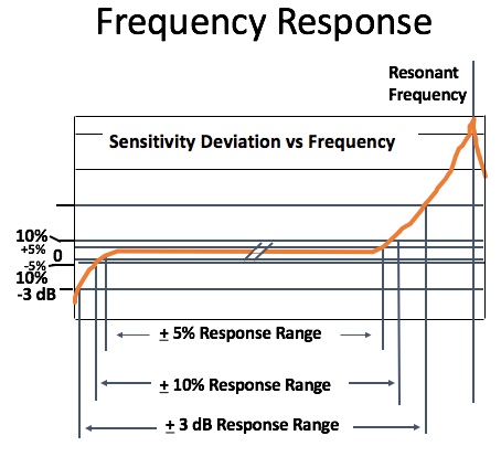 All PE accelerometers have a similar frequency response characteristic in that the output falls off at low frequencies and rises to a resonant peak at some higher frequency, but there is a useable range in between where the response is flat. This flat range determines where the individual accelerometer derives the quoted frequency response range. Although it is unwise to use an accelerometer to measure frequencies close to its resonant frequency, it is possible to get a measurement albeit ‘amplified’, by using it beyond the quoted upper frequency limit. The frequency response characteristic is repeatable and therefore the accelerometer can be calibrated at specific higher (or lower) frequencies to allow accurate measurement outside of the specified range, however for some applications it is not necessary to know the precise amplitude of the high frequency signals but merely to know when they are present.
The laws of physics determine the resonant frequency of any mechanical structure and so to maximise the resonant frequency of a piezo-electric accelerometer there must be a compromise between increasing stiffness and reducing physical size. Hence, the resonant frequency limit of 95kHz has been reached in the design of PE accelerometers. Whenever frequency response is quoted there should be two figures given; a reference frequency and a frequency range which relates to the two on the frequency response curve at which the sensitivity deviates by a fixed amount from that measured at the reference frequency. This sensitivity deviation amount is an arbitrary value depending upon the accelerometer manufacturer, so can be quoted as a percentage or a dB ratio e.g. ±5%, ±10%, or ±3dB. When quoting upper frequency response values, the 3dB deviation can appear significantly more impressive (higher frequency) than the 5% deviation, so care must be taken when comparing ‘like for like’ between different specification sheets.
When choosing an accelerometer, it is important that the frequencies to be measured are encompassed within the quoted frequency response figures in the specification. Historically, there has had to be a compromise between low frequency and high frequency response in an accelerometer. The introduction of ‘dual element technology’ now combines a DC and a PE accelerometer into a single sensor, giving a seamless cross-over from static to high frequency response.
-
Weight & Size
Generally, the larger the accelerometer the higher the sensitivity and improved low frequency response. For large structures the size of the accelerometer poses no problem, but for light weight structures the mass of the accelerometer can change the vibration characteristics to the point that the sensor is not measuring the ‘true’ vibration. There are also many applications where the size of the accelerometer is important and so miniature and ultra-miniature designs are available that can be installed in tight spaces. General purpose accelerometers are designed for use in the many applications where size and weight are not an issue, and much more rugged sensors are available for industrial use.
-
Temperature
The user will need to consider the temperature that the accelerometer will experience during the test. There is the obvious need to specify an accelerometer and appropriate cable with an operating temperature range encompassing the test requirements, however thermal sensitivity effects should also be considered if the temperature will vary significantly during the testing – check the thermal sensitivity variance on the specification sheet.
The operating temperature of a PE accelerometer, for now setting aside limits imposed by IEPE circuitry, is mainly governed by the type of piezo-electric material used. Quartz is chosen for very low temperatures due to its excellent stability. All of the synthetic ceramics with the ability to be polarised for use as a piezo-electric material have what is known as the Curie temperature at which the material loses the polarization and reverts to being just a ceramic. Until recently the piezo-ceramics with high Curie temperatures tended to have low sensitivities, resulting in physically large accelerometers to produce a reasonable output, but with materials advances now there are more miniature high temperature PE accelerometers available. Very high temperatures above 500°C cause extra problems with a loss of insulation resistance due to oxygen deprivation to the PE crystal, however novel designs have overcome this.
Operating temperatures greater than 121°C pose another major restriction on IEPE accelerometers, which is due to the temperature limits of the microelectronics used in the integral amplifier circuit. There are some high temperature electronics capable of operating up to around 180°C, but these are generally used only in some ‘application specific’ accelerometers. Consequently, charge output PE accelerometers are usually employed in operating temperatures more than 121°C.
For the best accuracy measurements in high/low temperature environments the accelerometer should be calibrated at the temperatures in which it is to be used and there are calibration facilities that offer this service.
-
Mounting
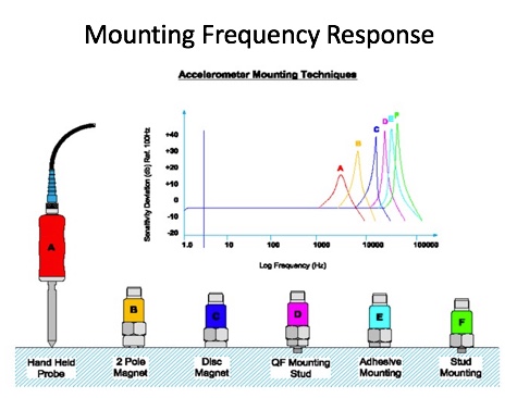 The mounting method of an accelerometer must ensure that the vibration and shock to be measured is transmitted faithfully to the sensor, and as the frequency of measurement increases this becomes more of a challenge. Ideally the accelerometer must be attached to a smooth, flat, and clean surface by a threaded mounting stud tightened to the recommended torque. A smear of grease or oil will help the mechanical coupling between the accelerometer and the test piece particularly where high frequencies are present. However, this ideal solution is often not practical and other mounting methods need to be employed. It is only possible to give guidelines for the user to follow and assess the prevailing conditions.
When using a mounting stud, it is important to use the stud provided with the accelerometer in order that all the frequencies are faithfully transmitted to the sensor.
When using an adhesive mounting method, it is in effect placing a cushion between the accelerometer and the test piece; this will only be effective for vibration transmission if it is both thin and rigid. Cyanoacrylate adhesive is most commonly used but care should be taken to select an adhesive suitable for the environmental conditions of the test (e.g. temperature/moisture). Where possible, use adhesive mounting bases and attach the base to the test article – the accelerometer may then be stud mounted to, and easily removed from, the base. If the accelerometer must be attached directly to the test piece, be cautious when removing. Use a solvent like acetone to first soften the adhesive, and do not use force that will either ‘over shock’ or distort the accelerometer casing.
The use of a micro-crystalline wax, sometimes referred to as “petro wax”, instead of adhesive is common for quick installation for vibration tests where the g level is not high, and high frequencies are not of interest.
Magnetic bases offer a very convenient method of attachment, but should be avoided if the frequency of the signal to be measured is greater than 2 kHz. A smear of oil or grease on the base of the magnetic base will help, but be careful that there is no dirt present. Fix the accelerometer to the base with the specified mounting torque and then do not allow the magnetic base to ‘snap’ onto the test piece, but place it on the surface at an angle and then roll it down into position. Never detach the magnetic base by pulling the cable.
Stingers and vibration probes vary in effectiveness in the way that different users will hold them, so care needs to be taken if using them.
Clamps and brackets can offer a convenient mounting solution, but be aware these will respond to any vibration or shock in accordance to their own resonances and damping, and it would be difficult to know whether the response of the structure or the mounting bracket was being measured.
Once the accelerometer is mounted the cable should be fixed or tied down at a location close to the accelerometer before routing it back to the signal conditioning, minimising the possibility for the cable to move or vibrate relative to the connector on the sensor.
-
Electrical Isolation
When 2 or more accelerometers are used simultaneously there is the possibility that, depending on where they are mounted, they could be at different electrical earth potentials. If so, ground loops can induce a large spike at mains frequency with harmonics, which can really mess up a measurement. The simplest solution is to use accelerometers that have their casing electrically isolated from their mounting base. The accelerometer specification should make it clear if the sensor is isolated or not. “Base isolated” means that the base is isolated from the housing, but the housing is common with the screen. “Case isolated” means that the complete housing and base is isolated from the cable screen. “Case grounded” means that it is a non-isolated design and the housing and base will carry the cable screen through to the test specimen. Isolated mounting bases are available for applications requiring electrical isolation but where there is not a suitable isolated design available.
-
Connector and cabling
A variety of different connectors are used in accelerometer design however the ‘micro-dot’ 10-32 threaded co-axial connector has remained the industry standard since accelerometers were first produced in quantity, simply because it has proved to be reliable in the face of vibration and shock. Many general-purpose designs use this connector, although the smaller 5-44 or 3-56 threaded connectors are used on miniature designs. Rugged industrial accelerometers tend to use a larger two pin design. Connectors can usually be fitted on the top or the side of the sensor, so this choice should be made depending on where and how the sensor is mounted. For shock applications it is often best to use a top mounted connector so that the shock loading is in line with the axis of the connector thread, or even an integral lead accelerometer with no connector at all. The integral lead wire accelerometer serves well for permanent, submersible and shock applications, and for the smallest ultra-miniature designs where a connector is not practical, but particular care should be taken if the sensor has to be removed and used again as the cable can soon get damaged.
The advent of the IEPE tri-axial accelerometer removed the need to have 3 separate micro-dot connectors on the sensor, so that a single 4-pin connector could be used and the industry standard 4-pin connector uses a ¼-28 thread. Take special care in cable selection for triaxial accelerometers as some designs of triaxial accelerometer do not have the same pin-out arrangement as others.
IEPE accelerometers, being low output impedance, can use ordinary co-axial cables, however these cables are prone to ‘tribo-electric interference’ when used with charge mode accelerometers. Tribo-electric noise is introduced when the cable is mechanically deformed allowing the build-up of local charge pockets, which discharge due to the movement of the cable. To prevent this, the outer jacket of the signal wire is coated with a conductive layer to dissipate any local charge build up to the screen of the cable. These treated cables are known as ‘low noise’ cables and have been designed for use with charge output accelerometers. It is recommended to keep these cables as short as possible and careful cable routing and fixing employed to avoid cable vibrations.
General purpose cables have a PTFE sheath and are flexible and easy to handle. The temperature and environmental specification of the cable should be checked to ensure that it will withstand the local conditions to which it will be exposed. Mineral insulated ‘hard-line’ cable will need to be used for very high temperature applications. Ruggedized cables with armoured jackets are available for harsh physical environments and chemical resistant cables should be selected if necessary.
-
Sealing
The environmental conditions in which the accelerometer is to be used will dictate the level of sealing that the sensor requires. Many accelerometers employ a glass to metal seal connector and are a fully welded design, so in effect are hermetically sealed, but the cable entry could still be a problem. Integral cables can be a solution, but epoxy sealing does not ensure a good watertight seal for very long.
-
Other parameters
Other parameters that may or may not be important include transverse sensitivity, which describes any effect that a sideways vibration may have on the primary measurement direction of an accelerometer. This can vary depending on the design of the accelerometer, but should be included on the specification.
Strain sensitivity may also be important if the accelerometer is mounted on a surface that is likely to experience large strain levels during vibration. As mentioned before shear mode designs help reduce this problem significantly.
Magnetic sensitivity is often quoted on specification sheets for consideration in high magnetic environments.
Accelerometer Calibration
The only way of being sure that an accelerometer is accurately measuring across the quoted frequency range is by calibration to a national standard that gives a level of confidence that the sensor is giving an electrical output which is faithful to the mechanical input. Currently, the highest frequency that any accelerometer may have a traceable calibration to is 20 kHz, which in theory says that nothing exists beyond this frequency. However, in practice this is not the case, and there are methods available to correlate the amplitude readings of accelerometers used above 20 kHz, but most accelerometer manufacturers do not quote frequency response figures above this frequency for this reason.
The time interval between accelerometer recalibrations is entirely down to the user. For general purpose use it is recommended to recalibrate annually, however for high usage applications or if the accelerometer is operated close to its specific limits for long periods of time this interval could be shorter, and for shock or crash test applications it is sometimes considered necessary to recalibrate the sensor after every test. The sensor should also be recalibrated if it has been known to exceed any of its specified limitations.
This article is a brief summary of what a piezoelectric accelerometer is and what parameters need to be considered when choosing the most suitable sensor. However for extra help with this, please contact us here at Techni Measure for our free advice.
 D5 Creation