
Unlike traditional vibration test controllers that rely heavily on an external computer for real-time operation, the Spider-81 is the first vibration controller that directly integrates time-synchronised Ethernet connectivity with embedded DSP technology.
This strategy greatly increases the control performance, system reliability and failure protection of the vibration test controller. It also allows a large number of channels to be configured without sacrificing system performance.
Latest Hardware Design
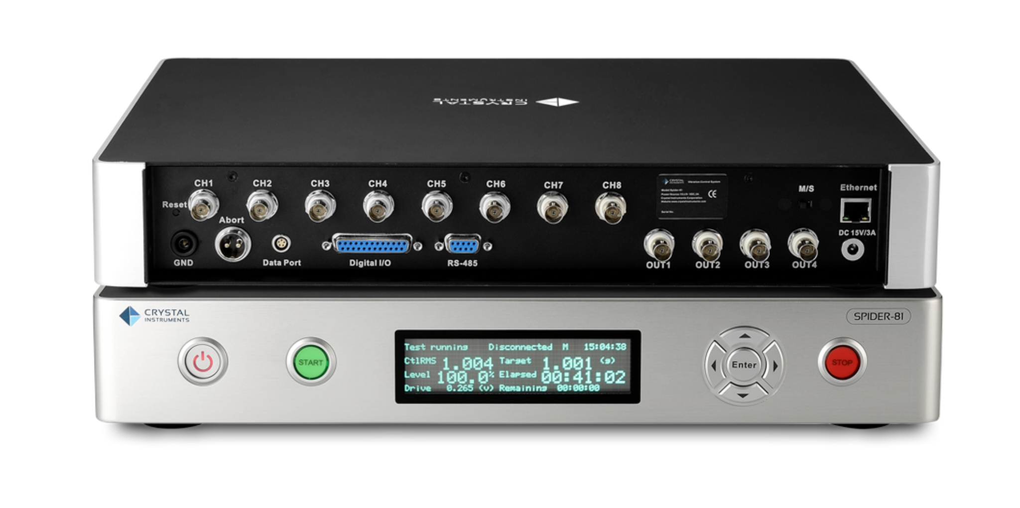
Spider-81 vibration test controllers have voltage, charge, TEDS, and IEPE inputs which are ideal for shock, vibration and acoustic measurement or general purpose voltage measurement. The internal flash memory stores test configuration data for controlling up to 64 channels simultaneously, in addition to storing real-time analysis data. Multiple output channels provide various signal output waveforms that are synchronised with the input sampling rate. A bright LCD screen displays testing status information. Ten monitoring connections on each unit are used to read signals of analogue inputs and outputs. Built-in isolated digital I/O and RS-485 serial ports enable interfacing with other hardware.
Simple Network Connection
Ethernet connectivity allows the Spider-81 vibration test controller to be physically located far from the host computer. This distributed structure greatly reduces the noise and electrical interference in the system. One computer monitors and controls multiple controllers over the network. Since all the control processing and data recording are executed locally inside the controller, the network connection will not affect the control reliability.
Time Synchronisation Between Multiple Test Controllers
The Spider-81 vibration test controller is built on IEEE 1588 time synchronisation technology. Spider-81 vibration test controllers on the same network are synchronised within nanoseconds. With such unique technology and high-speed Ethernet data transfer, the distributed components on the network truly act as one integrated system.
Product Specifications:
| Hardware Platform | Spider-81 | Spider-81B |
|---|---|---|
| Application | VCS, DSA* | VCS, DSA* |
| Max Sampling Rate | 102.4 kHz | 102.4 kHz |
| Number of Front-Ends Per Chassis | 1 | 1 |
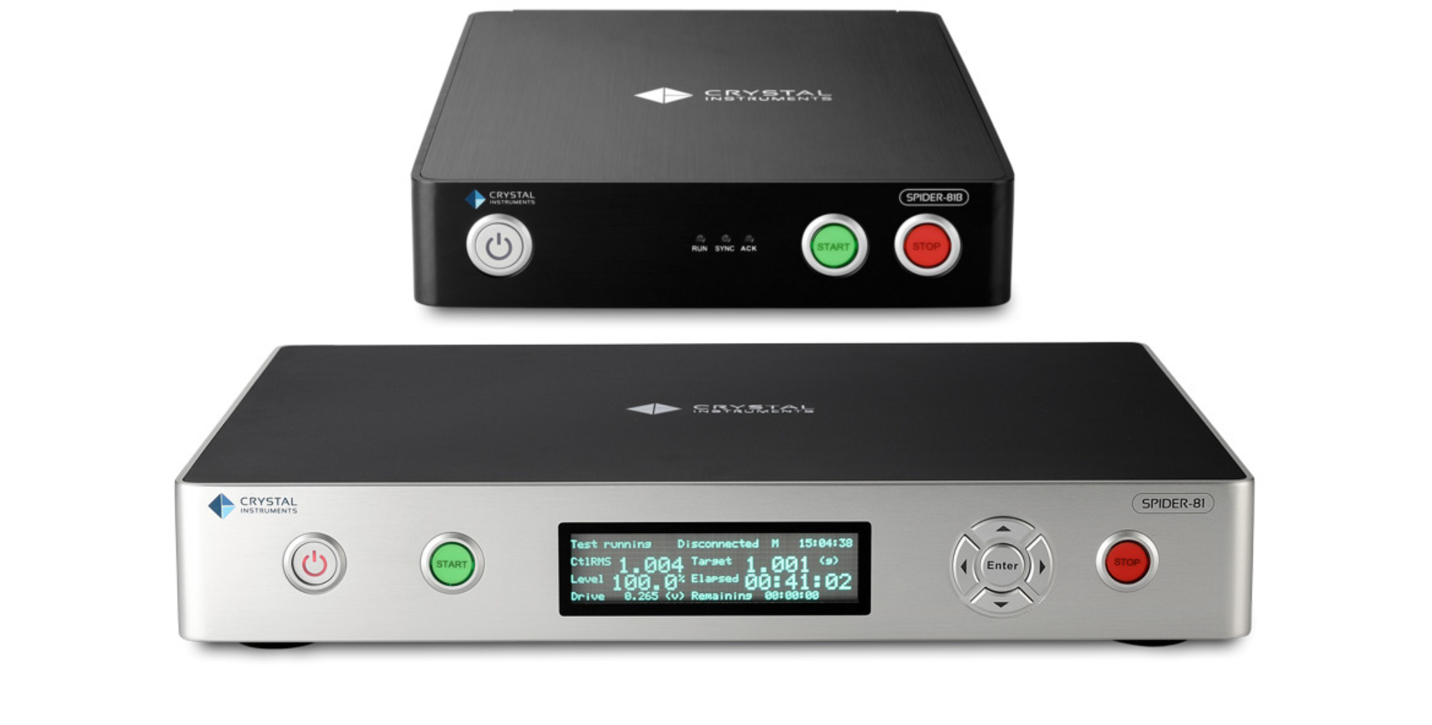
| Number of Inputs Per Front-End | 8 | 4 |
| Max Number of Inputs Per Chassis | 8 | 4 |
| Max Number of Inputs Per System | 512 | 4 |
| Number of Outputs Per System | 4 | 1 |
| Input Mode | Charge TEDS IEPE Voltage |
Charge TEDS IEPE Voltage |
| Digital I/O | 8 in/out, isolated | 4 in/out, isolated |
| Front Panel LCD | Yes | No |
| High Speed Data Port | Yes | No |
| Notes | Flagship product for VCS line. Input protection up to 250 V. Equipped with Stop/Start button. |
Economical solution |
")