

- Spider-80Ti is equipped with a 24-bit Sigma-Delta Analogue to Digital Converter (ADC) per channel to ensure highly accurate temperature measurements with any type of sensor. Together with the user-configurable non-linearity correction, the accuracy of the measurements is ensured over a wide range of temperature measurements.
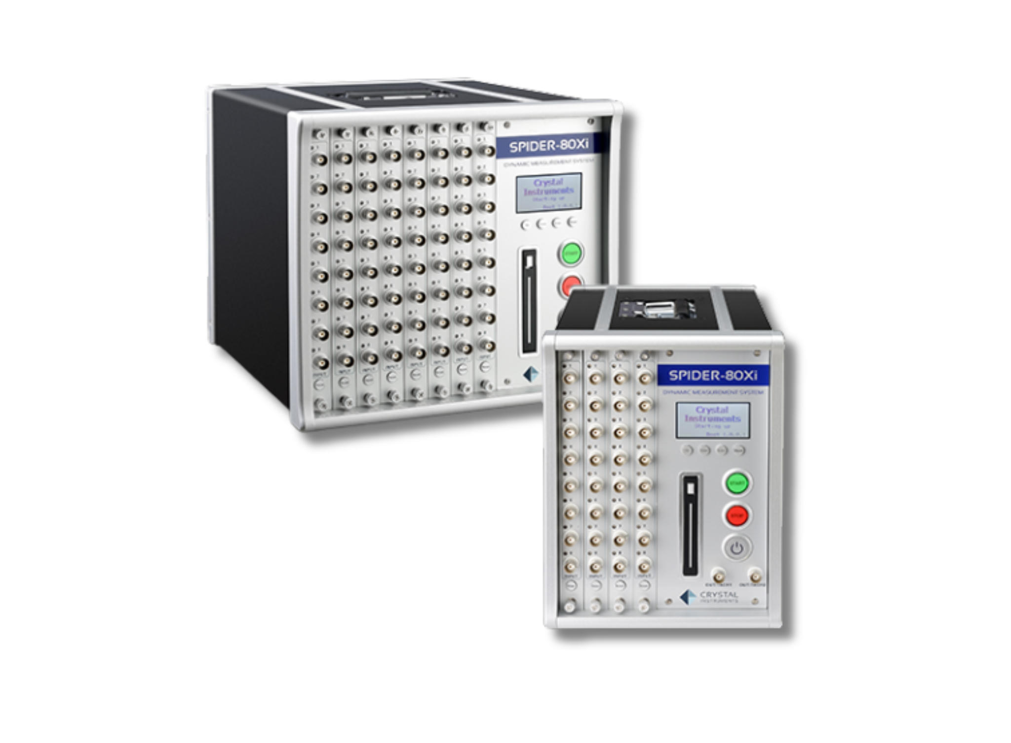
- The Spider-80Xi chassis can either be configured exclusively for temperature measurements using the Spider-80Ti front-end or can be configured for mixed signal data acquisition by combining the Spider-80Ti with Spider-80Hi, Spider-80Ci, or Spider-80SGi. A choice of Spider 80Xi chassis with 4 front-end slots or 8 front-end slots is available.
- The efficient design of the Spider-80Xi chassis eliminates individual enclosures for each modular front-end to minimise the overall dimensions of the system. Its lightweight design makes it ideal for applications requiring portability and an efficient size without the need to exchange front-ends during operation.
- Multiple chassis, consisting of Spider-80Ti front-ends or a combination of Spider-80Ti, Spider-80Hi, Spider-80Ci, or Spider-80SGi, can be connected to form a system with up to 1,024 channels, all sampled simultaneously at a rate of up to 512 Hz.
- The Spider-80Xi system is equipped with powerful and flexible data acquisition functions. Users can initiate continuous time data recording or data recording triggered by user-configurable events, including pre-set run schedule, alarm limit trigger, input trigger, or digital input trigger. A high-performance removable 2.5-inch solid-state drive (SSD) is used as storage media inside Spider-80Xi.
- The default capacity of the SSD is 250 GB and is extendable up to 2 TB. When recorded, data will be written in the NTFS file format. Data is extracted from the SSD using Crystal Instruments PC software to transfer data to the PC, or the SSD can be physically removed and connected to another PC.

Terminology
Maximum and minimum specifications characterise the warranted performance of the instrument within the recommended calibration interval and under the stated operating conditions. These specifications are guaranteed by design.
Typical specifications would be met by the instrument within the recommended calibration interval at the specified operating conditions. These measurements are taken during production verification of the finalised engineering prototype. The performance of the instrument is not warranted.
All performance specifications are typical unless otherwise noted. These specifications are valid within the full operating temperature range. Accuracy specifications are valid within ±5 °C after calibrating the unit unless otherwise noted.
Selection of Temperature Sensors
| Sensor Type | RTD | Thermocouple |
|---|---|---|
| Temperature Range (typical) | -200 to 650°C | 200 to 1750°C |
| Accuracy (typical) | 0.1 to 1°C | 0.5 to 5°C |
| Long-term Stability |
Good Stable and repeatable |
Variable Drifts because of oxidation |
| Linearity | Fairly linear | Non-linear |
| Power Required | Constant voltage or current | Self-powered |
| Reference Junction | Not Required | Required |
| Response Time |
Generally slow 1 to 10s |
Fast 0.10 to 1s |
| Susceptibility to Electrical Noise | Less Susceptible | More Susceptible |
| Cost | High | Low |
Most resistance temperature detectors (RTDs) are designed to measure temperatures up to 500°C, while thermocouples can operate over a much broader and higher temperature range. Depending on the table and measurement conditions, the appropriate sensor can be selected. Additionally, with two or more front-end modules, both types of sensors can be utilised (one sensor type per module).
