
Introduction to Strain Gauges and their usage
You can also download this guide: Download PDF
Techni Measure Online Store offers the facility to purchase some of our most popular strain gauges an accessories with next working day delivery and credit card payments.
Strain Gauge Applications
Strain gauges are used to determine or verify component or structure stresses, or by manufacturers of load cells, pressure and torque transducers, etc., where they utilise the physical parameter being measured to strain a part of the transducer in a linear way.
Strain
Stress itself cannot be directly measured but strain can, and for many materials within their elastic limit, there is a linear relationship between stress and strain. For uniaxial loading conditions, stress divided by strain is a constant known as Young’s Modulus of Elasticity for the material. Thus, if strain can be measured, stress can be calculated.
| Strain | Percent Strain | Microstrain |
| ·00005 | ·005 | 50 |
| ·0005 | ·05 | 500 |
| ·001 | ·1 | 1,000 |
| ·02 | 2 | 20,000 |
| ·1 | 10 | 100,000 |
Strain is defined as the linear deformation of a material. It can occur as the result of the application of force or of temperature change. Unit Strain, e, is the ratio of change in length divided by original length. This or dimensionless ratio is generally a very small decimal fraction, and is therefore usually multiplied by 106, becoming “microstrain”, me. Percentage strain is a term also used and the table below gives some conversions.
Strain Measurement
Strain can be measured using many techniques, but the resistance strain gauge is generally the most direct and convenient tool. Once bonded to the surface of the material, any physical strain in the material is transmitted to the strain gauge’s resistive element. This then experiences a proportional resistance change which in turn can be measured using appropriate instrumentation.
Strain Gauge Types and Construction
Both wire and foil strain gauges take the form of a grid pattern mounted within or onto an insulating carrier, capable of faithfully transmitting the strain from the specimen. Weldable gauges have their resistive elements mounted onto a metal carrier. Gauges can often be supplied with their elements heat treated to provide temperature compensation for use on different materials.
The foil gauge consists of a metallic alloy film laminated onto an insulating carrier. In a similar way to printed circuit manufacturing techniques, this metallic deposit is masked and then etched to leave a resistance grid. A very wide variety of shapes and sizes is possible with this manufacturing technique and different alloys and base materials offer a wide selection of gauges most suited to specific temperature or measurement applications. Special configurations are available which provide two or three separate grids precisely located with respect to one another. Active gauge lengths are available from 0·2mm to 30mm, and resistances vary from 60W up to 2000W.
The wire gauge consists of a grid of fine wire sandwiched between very thin insulating membranes. This carrier serves as a support and protection for the grid and also as an electrical insulator between wire and test surface. Gauges are available with nominal resistance generally of 120W in gauge lengths up to 120mm. Special configurations are also available which provide two or three separate wire grids on one carrier. Except for special applications, the wire gauge has been largely superseded by the foil gauge.
The weldable gauge is designed to be spot welded to a metal test specimen. Minimal surface preparation is required which enables fast application. Its construction makes it most useful for measurements in harsh environments for long periods, or at very high temperatures. Gauges are normally available in effective gauge lengths from 6mm to 16mm but generally only as single elements. Resistance values are usually 120W or 350W.
Choice of Gauge
There may be an application – specific gauge designed for a particular measurement task such as residual stress determination, bolt force or internal concrete strain evaluation. Otherwise, for general strain measurement, the choice must be made according to several criteria. These include anticipated strain level, operational temperature, installation and test environmental conditions, material being tested, temperature compensation, specimen and strain gauge carrier compatibility with chosen adhesive, and finally, gauge length. A short gauge length should only be chosen where the size of the specimen or expected stress concentration so dictates. Specimen materials formed of compacted or bound materials (cement, concrete, chipboard etc.) require gauge lengths to be at least three times that of the maximum particle size but, apart from this consideration, there is no advantage in choosing a long gauge. In general, ease of handling and installation, adhesive application, space availability and adequate performance will suggest a foil gauge of between 3 and 10mm for use on metals.
Gauge area, in conjunction with gauge resistance has also to be taken into account when total instrumentation stability is considered. The gauge’s resistance and excitation voltage both dictate the power being generated at the gauge, which along with the gauge’s area will determine the power density. The amount of heat generated should be sufficiently small so that, over the period of measurement, there is acceptable temperature stability. As a guide 0·005 watts/mm2 would be acceptable for static tests on metal specimens using foil gauges where moderate accuracy was required. Foil gauges, by having a greater surface area/resistance ratio, can dissipate heat better than wire gauges of the same size. Metal specimens are better heat sinks than (e.g.) plastics, whilst short term or dynamic measurements require less fundamental accuracy than those of static conditions or long-term duration, so that the recommended power density figure can vary.
Measurement Method and Formulae
The mechanical strain experienced by the test specimen, and thus also by the strain gauge, gives rise to resistive strain of the gauge element. The special alloys used in strain gauges exhibit a near-linear ratio between their resistive and mechanical strains. This ratio is known as the Gauge Factor and is approximately equal to 2·0 for foil and wire strain gauges. The value will be printed on each pack of precision strain gauges.
i.e.
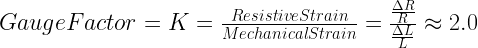
It follows that, if the resistive strain can be measured, and with the gauge factor known, the mechanical strain can be calculated and the stress subsequently deduced. Using a conventional resistance-measuring meter, it would be difficult even to detect, let alone accurately measure, the small change of 0·12 ohm (= 0·1%) caused by 0·05% mechanical strain of a 120 ohm gauge. The Wheatstone Bridge circuit, shown in its basic form in fig. 1, is a network of four resistances, one of which is an active strain gauge. When the ratio of resistances is equal to that of the Bridge is said to be “balanced” and the voltage output is zero. When the resistance of the strain gauge changes, the Bridge becomes unbalanced and a voltage output is created. Even though this may be small, it is a change from zero and can be amplified and measured using appropriate instrumentation.
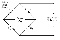
Fig. 1
It can be shown that for the circuit shown in Fig.1, the open-circuit output voltage 
the input voltage E multiplied by the factor and so, when R1R3 = R2R4 ,
For the convenient case where R = R1 = R2 = R3 = R4,
if R1 changes to R +

and if we ignore 2

and since 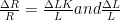

For a two-active arm Wheatstone Bridge such as that shown in fig 8a, 
four-active arm bridge such as is shown in Fig 8b,
Practical strain measurement
Balance – in order to be able to commence strain measurement with a zero output, it is necessary to balance the Bridge which will invariably have some initial imbalance due to the small variations in resistance found between the various gauges and fixed resistances of the Bridge. This can be accomplished by using a low resistance potentiometer P1 in series at a bridge apex (Fig. 2) or by having a high resistance potentiometer P2 circuit across opposite apexes (Fig. 3). Both balancing circuits are shown in their simplest forms and there are several more complex variations.
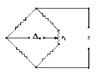
Fig. 2
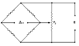
Fig. 3
Alternatively, the unbalanced Bridge output voltage can be “backed off” by an equal and opposite voltage generated within the instrumentation.
Calibration – The gauged specimen’s strain output may be calibrated by loading or straining the specimen in known increments and recording the electrical output with known input voltage. The recording equipment should be that with which the strain-gauged specimen will ultimately be used. The relationship of output against load or strain is subsequently used for the evaluation of actual test results.
Another method is to cause Bridge imbalance by shunting a high resistance in parallel with one of the arms of the Wheatstone Bridge. This creates a precise amount of resistive “strain” which therefore represents a known mechanical strain. The value of the resistance RS necessary to simulate the output due to a mechanical strain e at the active gauge is found from the approximate formula 
Single Gauge Applications – For this use of strain gauges, only the one gauge is performing the measurement and it is general practice to have R3 & R4 of the Wheatstone Bridge as fixed, high stability, resistors within the instrumentation where they will remain unaffected by any environmental changes.
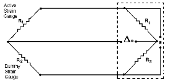
Fig. 4
The active gauge R1 is remote from the instrumentation, and both it and its associated wiring are subject to resistance changes brought about by any variation in temperature. In order to compensate for such changes (which the instrumentation would interpret as mechanical strain) the gauge itself should be chosen, if possible, as one having temperature compensation for the material being tested. R2 is made to be a “dummy” strain gauge of the same type as R1, by mounting on the same type of material, but unstrained. The dummy should be placed as close as possible to the active gauge, so that both it, and its associated wiring, will experience the same temperature changes as the active, such that identical effects on the two adjacent arms of the Bridge will cancel each other out.
When it is not practicable to employ a dummy gauge in this way, it would not be good practice to have dummy R2 within the instrumentation and the active R1 connected to the Bridge using only two wires, because temperature effects on those wires would cause inaccuracies. In such cases it is good practice to employ a “3-wire” lead to the gauge. That shown in Fig.5 is one of several variants.
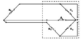
Fig. 5
In this arrangement, both the active gauge R1 and resistance R2 have an equal length of lead wire in series, so that temperature effects on lead wire resistance are cancelled out. It should be remembered however that the use of long lead wires will reduce the sensitivity of the system.
Multi-gauge and Transducer Applications – Single gauges can only be used, with the assurance of being able to calculate stress from measured strain, when that stress is uniaxial and its direction known. In biaxial stress fields, it is necessary to know the strains along the two principal axes before the stresses can be calculated. If the orientation of these axes is known, then two gauges only (a 0°, 90° pair) need to be used, but if orientation is uncertain, strain measurement in at least three directions has to be made in order to make the calculation. Three-gauge rosettes are available for this purpose, having resistance elements at 0°, 45° & 90°.
Measurement of Axial Strain Independent of Bending Strain
Fig. 6
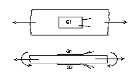
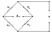
For certain components or structures, it may be necessary to know the value of solely the axial strain. If a bending moment is also present, a single gauge would be unable to make the required measurement. If a pair of active gauges G1 and G2 can be mounted on the component and arranged in the Wheatstone Bridge as shown in Fig. 6, the equal and opposite effects of bending on each gauge will cancel each other out, leaving a net resistance change proportional only to the axial strain.
Measurement of Axial Strain, Independent of Bending Strain but with Full Temperature Compensation & Increased Output Voltage
Fig.7
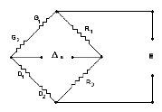
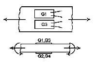
In the arrangement shown in Fig. 7, the equal effects of axial strain on gauges G1 and G3 are additive whilst the mutually opposite effects of bending cancel each other out. The transverse gauges G2 and G4 (which individually would measure the “Poisson” strain) each contribute that fraction (0·285 for steels) to the Bridge output which would therefore be 2·57 times that of a single active gauge in (non-bending) axial strain. The transverse gauges also serve to provide full temperature compensation and the arrangement therefore becomes suitable for use in a simple load cell.
Measurement of Bending Strain Independent of Axial Strain
Fig. 8a
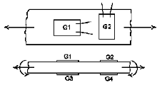
In this two-active-arm arrangement, the equal effects of axial strain on G1 and G2 are cancelled out and the bending effects are additive, giving a bridge output double that which would derive from a single gauge in pure bending. The arrangement also provides full temperature compensation.
Fig. 8b
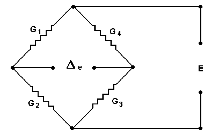
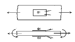
In this four-active-arm arrangement, axial strain effects are again cancelled out and bending effects are additive thus giving a four-fold sensitivity compared with a single gauge. Foil gauges can be supplied as parallel pairs of elements on a single carrier thus eliminating the task of having to bond two gauges side-by-side in precise location and orientation relative to one another.
Measurement of Torsional Strain Independent of Axial or Bending Strains
Fig.9
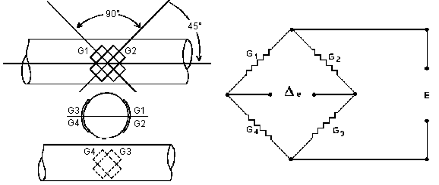
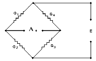
In this four-active-arm arrangement, the equal and opposite shearing strains of each gauge pair also give a four-fold output whilst any effects due to axial or bending strains and temperature are cancelled. Several patterns of gauge suitable for this type of measurement are available, with element resistances up to 2000 ohms.
INSTRUCTIONS FOR BONDING STANDARD TML STRAIN GAUGES TO STEEL
- An area larger than the gauge to be bonded should be cleared of rust, scale, paint, etc. and polished with abrasive paper (approx. 200 grit) or a fine grinding tool. Final abrasion should be cross-hatched at about 45° to the measurement axis.
- Thoroughly degrease the area with a solvent such as acetone, methyl ethyl ketone or isopropyl alcohol using clean cotton buds. (Ensure good ventilation when using solvents.) Repeatedly apply the solvent and wipe off with fresh cotton buds until the final wipe is stain free. Use continuous strokes working from the centre of the area to avoid picking up grease from the surrounding specimen. If the gauge backing has been handled, that should also be degreased with solvent. Use blunt, cleaned tweezers to handle the gauges.
- Lightly mark location lines on the specimen using a ball point pen, and clean off as in (2). Avoid marking where the gauge grid is to be placed.
- Place the gauge with grid and terminals upwards on a thoroughly cleaned surface together with the solder terminals, if used, ensuring the lead wires are on top of the terminals. Place a strip of adhesive tape (about 100mm long, dependent on the gauge length) over the strain gauge and terminal strip, then carefully lift the tape with gauge attached at a shallow angle, taking care not to bend the gauge excessively. (Fig.1)
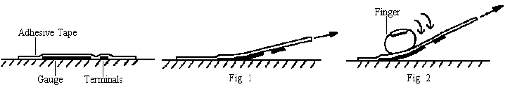
- Transfer the gauge and terminals to the specimen and position the alignment marks with the location lines on the specimen. Carefully lift the tape (Fig.1) with the gauge and terminal, leaving one end of the tape still adhered to the surface. Take care not to bed the gauge excessively.
- Apply adhesive as follows. Always refer to manufacturer’s instructions.
- CN cyanoacrylate adhesive recommended for post yield and GF plastics gauges and applications where a fast bond is required. Apply a drop of adhesive to the gauge and to the terminal. Rapidly roll the gauge onto the specimen, pushing the adhesive along the gauge in one smooth action (Fig.2), ensuring no air is trapped under the gauge. Quickly cover with the polythene square supplied, and apply strong finger pressure for at least one minute. When bonding Y series gauges, a pressure (approx. 5kg/cm²) should be applied for 3 minutes. Leave gauge for 3 minutes before carefully peeling off the adhesive tape.
- P-2 polyester adhesive for long term requirements. Mix the adhesive and hardener as directed in manufacturer’s instructions. Apply adhesive with clean spatula to the gauge, terminal and specimen. Position carefully and roll gauge onto specimen, pressing out excess adhesive and air bubbles. Cover gauge with polythene square supplied, and apply a pressure (approx. 2kg/cm²) using a metal backed rubber cushion to spread the load. Leave for at least 30 minutes. After setting, peel off the adhesive tape.
- NP-50 adhesive for high temperature. Proceed as for P-2 and post cure if required.
- If stuck, the lead wires should be carefully pulled out of the adhesive before soldering.
This is a suggested method of gauge bonding, which may not be convenient or appropriate in all circumstances. Sometimes it is preferred to proceed without using the adhesive tape to locate the gauge, but this requires rather more skill than the above method. Alternative cleaning chemicals may be used, but it is important to obtain a clean, grease-free, dry specimen before adhering the gauge. For further advice on any aspect of strain gauge selection and use, gauge bonding – especially on other materials, environmental protection and amplifier systems.
 D5 Creation